Our mirrors come Non-Dimmable “default” LED power regulator that can be hard-wired directly to a wall switch. The electrical connections are very simple:
Non-Dimmable Regulators
- Please note that if you have a large mirror, you may have TWO power regulators. These will be wired exactly the same way as a single power regulator, the only difference will be that you will have two lengths of LED string instead of one, each connected to a power regulator.
- One side of your regulator connects to a standard Romex wall circuit, 14/2 or 12/2. This will be the side with the unconnected wires coming out of the regulator (see below). If there are two power regulators, the wires will be wired together for a single hot and neutral connection. Typically, you will have 18-22 inches of play in the connection wire to extend to the Romex electrical wire coming out of your wall, and a very large space within the boundaries of the inside frame to locate your house wire. Our wiring may or may not include a plastic connecting block. The WHITE(or blue) neutral wire from the regulator wire connects to the Romex WHITE neutral wire. The BLACK(or brown) hot wire connects to the Romex BLACK hot wire.
- The other side of your regulator connects to the LED string that is installed in the frame of your mirror. Connections from the low voltage side of the regulator to the LED are very simple: RED to RED, BLACK to BLACK. If your mirror has a switch, the switch will also be connected to the LED wires to control electrical output to the LED based on whether the switch is turned on or off. Please see our switch installation blog for information on this wiring when it includes a switch.
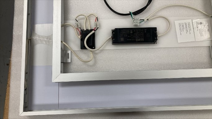
Non-Dimmable Regulator and Connections
(Note: See below example – PR model / qty may vary from example based on: size, model, and date ordered.)
Dimmable Power Regulator (DPR)
We offer an upgrade to install a Dimmable Power Regulator in your mirror at our warehouse prior to shipping you the mirror. There are two very important requirements to be able to use a DPR to dim your mirror:
- You must have two 14/2 Romex lines connected from your wall dimmer switch to the back of the mirror.
- One line will supply power, connected from your wall dimmer switch to your mirror.
- The other line will control the dimming function from your wall dimmer switch to your mirror.
- You must purchase and install a Leviton IP710-DLZ dimmer switch or compatible 0-10V dimmer control switch that will work with our LED technology. We have tested the Leviton IP710-DLZ. The wiring instructions are based on the Leviton model. Similar models will connect similarly but please review the dimmer control instructions carefully to make sure you are connecting to the proper wires.
Connecting the DPR (also see wiring diagram, below)
NOTE: If you purchase an LED mirror with the DPR upgrade, the DPR will come pre-wired to the mirror LED strips.
- Installing a DPR will basically be replacing your existing power regulator. If you have one regulator, you need one DPR. If you have two regulators, you need two DPRs.
- Remove the existing power regulators by unscrewing them from the white plastic mounting sheet and disconnecting them from the LED. If connected to the power circuit, these connections must also be disconnected (make sure to turn off power to the circuit at circuit breaker before disconnecting!).
- Attach double sided tape to each of the DPRs (see below) and mount them on the white mounting sheet in the same positions where the original regulators were installed.
Double Sided Tape on Back of DPR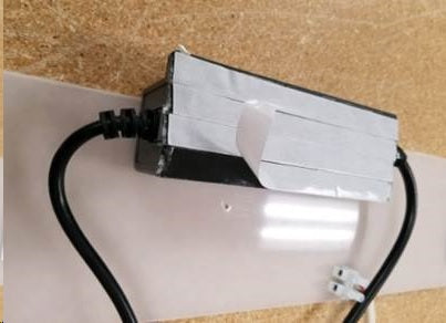
- Wire the house power circuit to the Input side of your LED mirror DPR and a compatible 0-10VDC wall dimmer switch.
- The BLACK wire from your house power circuit connects to the BLACK wire on your wall dimmer control switch.
- The WHITE wire from your house power circuit connects to the WHITE(or blue) neutral line coming from the Input side of your DPR (the side with only 2 wires - WHITE(or blue) neutral and BLACK(or brown) hot wire, see Diagram below).
- The BLACK (or brown) wire from the Input side or your DPR connects to the RED wire coming out from your compatible 1-10VDC wall dimmer switch (the red wire that is adjacent to the black wire, NOT the red wire that is adjacent to the gray wire).
- Wire your wall dimmer switch control to the Output side of your DPR (the control side). The Output side of your DPR has 4 wires. Two of these (the red and black wires) will be wired to your LED strips and the other two will be used to connect to your compatible dimmer control switch.
- The PURPLE OR BLUE (V+) wire from your compatible wall dimmer switch connects to the BLUE wire on your DPR.
- The GRAY or WHITE (V-) wire from your compatible wall dimmer switch connects to the WHITE wire on your DPR.
- Wire your DPR (Output side) to your LED strips. The connections basically mimic the same connections that your original standard power regulator have to your LED strips. BLACK (-) to BLACK. RED (+) to RED. If your mirror has a switch, wire the BLACK wire from the DPR to the BLACK wire on the switch, wire the RED wire from the DPR to the RED wire on the LED strip, and wire the RED wire from the switch to the BLACK wire on the LED strip.
- The GREEN wire (bluish green), from the dimmer control wall switch is the GROUND wire. The RED wire (with a label attached) from your dimmer control wall switch (the one adjacent to the gray wire) is for 3-way configuration.

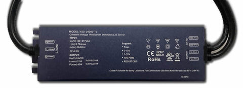
Dimmable Power Regulator (DPR)
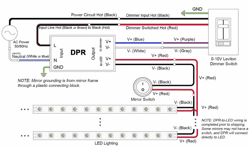
DPR Wiring Diagram
NOTE: The 0-10VDC wall dimmer switch wiring colors are based on our testing of many compatible brands, but it may not match the exact wiring colors for all brands or newer models.